
I am going to type the distance here, after which I am going to select the data flow V2, and then I am going to click Save, which will bring up our web dashboard and make cryogenic level indicator ready for use. I am going to navigate to the Storage tab. First, allow me to go to my device so that I can click here; then, allow me to click on the new device; and finally, allow me to select the name of the template from the template. In order to add a device at this point, we are required to use this template as a guide. You are also free to tell me the name of the device that I am utilizing at this very moment. Choose the Create Now button from the menu.
At this point, we need to connect all of these components in accordance with the circuit diagram because you will be using the sensor in the water tank. The circuit diagram can be found here. Either the waterproof ultrasonic sensor or the sr04 ultrasonic sensor is a valid choice for this application. In the event that you do not wish to make use of alternating current (AC) power, you will be required to make use of the AC to DC converter; in any other case, you will be able to supply the circuit with direct power of 5V. However, you are more than welcome to utilize the ultrasonic sensor in accordance with the circuit before designing the PCB for this project. For this project, we will be utilizing the waterproof ultrasonic sensor.
At this stage, we will begin to remove the cover from the board. It is now time for us to conduct an inspection of the terminal. To put cryogenic level indicator more plainly, it is a button that can be found on the front sensor. By using the right mouse button and then pressing the enter key, you will be able to bring up one of our four key menus. From this menu, you will be able to choose the unit and make a number of adjustments, such as the relay setting and the measurement unit. This image shows a portion of the sensor located on one of its sides. At this point, you should be familiar with all of the various applications that an ultrasonic liquid level sensor can have.
As a result of this, one of the things that I'd like to look into is whether or not there is a side calibration for twenty-four hours. It is absolutely necessary for me to shift the door to position 25 on the track as quickly as humanly possible. Because I calibrated it, Cryogenic level indicator is precisely set at 25, which is the distance from the beam path and the method for calibrating this. Because I calibrated it, it is exactly set at 25. Therefore, in preparation for this, I calibrated it. I have just uploaded the content; therefore, I would ask that you please watch it so that I can make any necessary adjustments after first expressing my regrets. I will make a drawing and a dac type, which stands for the distance amplitude curve, so how to draw the ds machine in this, so I must click to make the dhc, and I must enter the dac setting. I will then proceed to make the drawing. In order to learn how to enter the setting, I must first click the next group, then click the next group, and so on until I finally get the dac. Then, in order to learn how to enter the setting, I must go to the setting menu where the dac is located, which is in the customs.
For example, I am required toBecause I want three holes, the curve needs to have three points, and the calculation for the dac, which is a portion of the area that is not visible on the screen, has already been prepared. In point of fact, there are three holes on either side of the clock that was made in 1991.
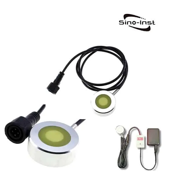
The procedure for connecting will involve the use of this component in some way
- The portion that is on the side looks like this
- At this point, we are in possession of black and red wires, which serve as the power supply for a DC 24V system
- As a result, we are going to begin with these cables that are coming from it
- Now that we have everything set up, we will first connect the 24V DC power supply, and then we will turn the power on
- Because of this, we will be able to turn on the power for our sensor
- You will find the positive and negative terminals for a 24 V DC supply on the right terminal
In addition to that, I provided an explanation of the version of each library. After you have completed that step, proceed to install this updated version. After you have entered the authentication token and the template ID device name, I will then take you to the Blink account. Please do not forget to enter the authentication token. It will only take a click on this link for me to copy each of these particulars, after which I will paste them in here. Following that, I will have to type in the Wi-Fi name and password in this box. It is impossible to adequately express how important it is that this component of the project be completed. When the tank is empty, the distance between the sensor and the base of the tank is equal to the distance between when the tank is full and when cryogenic level indicator is empty.